


【MR技术】磁共振信号是如何包含空间频率信息的?暨【Q&A in MRI】5.1.7(2)


由于频率编码梯度施加的同时进行信号的采集,那么信号的频率将依赖于被扫描物质在梯度磁场中的位置。
8.5 In-Plane Localization
8.5 平面内定位
In MRI we use the gradients to measure the two- (or three-) dimensional spectrum of the object being imaged. This spectrum is what we call k-space and consists of an array or matrix of individual spatial frequencies. The next sections will explain the process conceptually.
在磁共振成像中我们用梯度来测量被成像物体的二维(或三维)频谱。这一频谱就是所谓的 k 空间,由一组单独的空间频率所组成的数字矩阵。下面将从概念上来解释这一过程。
【译者注1】
【Q&A in MRI】5.1.6 Filling k-space k 空间填充

%%%%%%%%%%%%%%%
8.5.1 Spatial Frequencies Demystified
8.5.1 空间频率简述
The concept of spatial frequencies is not just a theoretical abstraction dreamt up to torment students of MRI. In real life the brain makes use of spatial frequencies to construct the visual images that you see. Spatial frequencies may be hard to conceptualize but they are very natural and we’d all be in the dark without them!
空间频率这一概念不仅仅是一个空想出来折磨磁共振学习者的抽象理论,在现实生活中,我们的大脑利用空间频率来建立我们所看到的视觉图像。空间频率理解起来可能很困难,但它们却又是真实存在的,并且如果没有空间频率的话,我们将处理黑暗之中!
One of the easiest ways of understanding spatial frequencies is to think of a line-pair test object, such as those used for testing X-ray imaging systems. These consist of alternate light and dark bands or line-pairs of differing spacings (Figure 8.10).
理解空间频率最简单的一种方法就是考虑一个线对测试卡片,比如用于测试 X 线成像系统的线对。它们包含明暗交替变化的条带或不同间距的线对(如图 8.10,即下图)。

%%%%%%%%%%%%%%%
【译者注2】
【Q&A in MRI】5.1.5 Location of Spatial Frequencies 空间频率的位置


%%%%%%%%%%%%%%%
Suppose we have five line-pairs per centimetre. This means that five dark–light patterns are contained within a centimetre. The pattern of image brightness produced by this line-pair pattern is like a spatial frequency. In MR a spatial frequency is a periodic variation in signal spatial distribution or image brightness, measured not as line-pairs per centimetre but as ‘cycles per centimetre’ (which are very similar).
假设每厘米有 5 个线对,这意味着在一厘米内有 5 组明暗条纹。这种线对模式产生的图像亮度模式类似于空间频率。在磁共振中,空间频率是信号或图像亮度在空间分布上的周期性变化,不是用每厘米线对数表示,而是用“每厘米周期数”表示(十分相似)。
%%%%%%%%%%%%%%%
【译者注3】
【Q&A in MRI】5.1.4 Spatial Frequencies 空间频率


%%%%%%%%%%%%%%%
Applying the theory of Fourier, any image (not just MRI) may be decomposed into a spectrum of periodic (sinusoidal) brightness variations or spatial frequencies. In a digital image with a matrix of 256 × 256 pixels there are 256 × 256 possible spatial frequencies, allowing for positive and negative values. If we know the spatial frequencies we can calculate an image of the object that formed them. The purpose of MR localization by gradients is to manipulate the MR signal so that it gives all the spatial frequencies necessary to form an image. Each point of data or k-space is a spatial frequency component.
任何图像(不仅仅是磁共振图像),应用傅立叶变换理论进行解析都可以分解成周期变化的亮度(正弦曲线形式)或空间频率。矩阵为 256 × 256 像素的数字图像将有 256 × 256 (=65 536)个可能的空间频率,可以是正值也可以是负值。如果我们知道某物体一幅图像的所有空间频率,那么我们可以计算出这个图像。用梯度进行磁共振定位的目的就是想要操纵磁共振信号,使之能够提供重建一幅图像所需要的所有空间频率。k 空间中的每一个点代表一个空间频率分量。
%%%%%%%%%%%%%%%
【译者注4】
【MR技术】为什么磁共振成像这么麻烦?或许这篇文章能够给你带来新意。
%%%%%%%%%%%%%%%
Figure 8.11 shows an image and its constituent spatial frequencies (k-space). If we remove the high spatial frequencies we are left with an image which has the right brightness but no detail. Removing the low spatial frequencies leaves the image with details of edges and sharp features but low intensity elsewhere. So big objects have low spatial frequencies. Small objects or sharp edges have high spatial frequencies.
图 8.11(即下图 a)展示了一幅图像以及它所对应的空间频率(即 k 空间)。如果我们将高频信息去除掉,那么得到的图像将只有亮度没有细节(即下图 b);如果去除的是低频率数据,那么得到的图像将会只包含图像边缘和一些尖锐特征,而图像整体的亮度将很低(即下图 c)。因此,大的物体对应低频信息,小的物体或锐利的边缘对应高频信息。

%%%%%%%%%%%%%%%
【译者注5】


大的物体对应低频信息,小的物体或锐利的边缘对应高频信息。从上面以及原文中的示例图就能够完全看出。另外,从下面 大圆 与 小圆 的 k 空间示意图中也能够完美表现:大圆的空间频率主要集中在低频区域,小圆拥有丰富的高频空间频率(k 空间调成相同的窗宽窗位观察)。


%%%%%%%%%%%%%%%
8.5.2 Totally Fazed: Phase Encoding
8.5.2 完全懵的概念:相位编码
Most people find phase encoding the hardest part of MR image formation to understand, but gaining a conceptual grasp of it will pay dividends in terms of your overall understanding. Consider the following in conjunction with Figure 8.12, which shows the effect of the phase-encoding gradient on the transverse magnetization at three different locations and times.
可能大多数人觉得相位编码是磁共振成像过程中最难理解的一环,但一旦你从概念上掌握了相位编码的话,那么对于你全面理解磁共振成像将获益良多。下面我们结合图 8.12(即下图)来理解相位编码。图 8.12 给出了在施加相位编码梯度时,三个不同空间位置的横向磁化矢量分别在三个不同时刻相位编码梯度对它们的作用效果。

%%%%%%%%%%%%%%%
【译者注6】


%%%%%%%%%%%%%%%
Suppose we already have an MR signal with all the spins in phase. If we apply the phase-encode gradient (GPE) at time A in the y direction, then the precession of the nuclei will speed up or slow down according to their position along the y axis. As we saw in Section 8.3.3, this causes the spins to dephase or fan out to a progressively greater degree for as long as the gradient is applied. When we switch off the gradient at time B, all the nuclei will revert to their original frequency or speed, but will keep their different phase angles. They are said to be phase encoded. The relative phase differences between signals in different locations remain until either another gradient is applied or the MR signal decays due to T2 relaxation.
假设一开始所有自旋的磁共振信号都是同相。如果我们在时刻 A 沿着 y 轴方向施加一相位编码梯度,那么所有的氢原子核的进动频率将加快或减慢,具体根据它们在 y 轴所处的位置来判断。就像我们在 8.3.3 节中讲过的,这一编码梯度将导致自旋开始散相或成扇形散开,只要梯度一直施加,那么散相的程度将一直持续增大。如果我们在时刻 B 关闭梯度的话,那么所有的氢原子核将又恢复到它们原来的进动频率,但它们不同的相位角将得到保留。这一过程就称作相位编码。而这一不同位置质子群信号相对的相位差异将一直保留,直至另一个梯度的出现或磁共振信号由于 T2 弛豫衰减完毕。
%%%%%%%%%%%%%%%
【译者注7】

%%%%%%%%%%%%%%%
Figure 8.13 shows the phase encoding generated by three different gradient amplitudes on a column of protons in the phase-encode axis. We see that without any applied gradient, the spins are all in phase and a large signal is obtained, but that the dephasing or twisting of the spins increases with gradient strength until the dephasing is large enough for all the spins to cancel each other out and no signal is obtained.
图 8.13(即下图)显示了在相位编码梯度方向沿柱形分布的质子群所经受三个不同梯度场强度而产生的信号差异。我们看到,在没有施加梯度时,所有质子群均同相,并且采集的信号强度很大(即下图 a)。但随着梯度强度的增大,质子群的散相也越来越大,当散相足够大使得所有质子群的相位相互抵消时,那么将没有磁共振信号产生。

%%%%%%%%%%%%%%%
【译者注7】
%%%%%%%%%%%%%%%
How is this measuring spatial frequencies? Referring to Figure 8.13, suppose we have a uniform distribution of protons and we apply a sufficient phase encode gradient to cause the phase of the spins to vary by 360° (2π radians or multiples of 2π). When we add up the MR signal from this column we get zero as the spins are evenly distributed throughout each direction. We can say that this object contains no information at the spatial frequency of one cycle per unit length.
那么这又是如何测量空间频率的呢?参考图 8.13,假设质子群均匀分布,并且我们施加一个足够强的相位编码梯度,使得所有质子群的相位变化范围为 360°(2π 弧度或 2π 的倍数)。由于所有自旋平均分布于各个方向,当将这一圆柱内的所有质子的磁共振信号相加时我们将得到零信号。那么我们说这个物体没有单位长度一个周期的空间频率信息。
Consider now a series of line-pair structures as in Figure 8.14 with alternating sections containing protons or nothing.
下面我们来看看一系列线对结构(包含质子与不包含质子交替排列),如下图 8.14 所示。

Obviously only the sections containing protons can contribute to the signal. In the instance where k = 8 due to their distribution in space they are in phase and add up to give a net positive signal. That is to say, this particular value of phase encode gradient is sensitive to objects containing the spatial frequency eight cycles per FOV. Looking at the other patterns in Figure 8.14, none of the lines add up to anything other than zero.
很显然,只有含有质子的那部分对磁共振信号有贡献。例如上图,当 k = 8 时,由于质子的空间分布是同相的,那么叠加起来时将会产生一个净的明确的信号。也就是说, 这一特定的相位编码梯度对在 FOV 大小内八个周期的空间频率敏感。再看图 8.14 中的其他线对模式,加起来的信号都是零。
%%%%%%%%%%%%%%%
【译者注8】

%%%%%%%%%%%%%%%
In general, however, an object (i.e. the patient) will have a range of spatial frequencies. Each value of phase encoding can be considered as a template or a comb (technically, a filter) that only responds to one spatial distribution of MR signal or spatial frequency. To build up a whole picture, the entire range of possible spatial frequencies has to be interrogated. This is achieved by stepping through all the values of phase encoding (the ‘ladder’ in Figure 8.1), once per TR period. When no gradients are applied, we get a signal from the whole object, and this is referred to as the zero spatial frequency or zero k.
然而,通常一个物体(如病人的身体)所拥有的空间频率是一个范围。每一个相位编码值可以看成是一个模版或一把梳子(用专业术语叫滤波器),对应于磁共振信号的一个空间分布或空间频率。如果要重建一幅完整的图像,就需要包括所有可能的空间频率。通过逐步采集所有相位编码来实现(如图 8.1 中用“梯状图形”来表示相位编码),一个 TR 间期采集一个相位编码。当没有施加梯度时,采集的整个物体的信号称之为零空间频率或 k = 0.


So the MR sequence consists of multiple repetitions of the excitation process followed by a different phase-encode gradient until all possible spatial frequencies are collected. You can think of each phase-encode step as being a filter or a comb, as in Figure 8.15. Once all these signals are collected, the application of a Fourier transform converts the spatial frequency distribution into a spatial distribution of the excited nuclei, i.e. an image of the patient.
因此,磁共振成像序列包含多个射频激发过程,而每一次射频激发都匹配一个不同的相位编码梯度,直至所有可能的空间频率都被采集完。你可以将每一个相位编码步长想像成一个滤波器或一把梳子,就像图 8.15 中所示。当所有信号都采集完,通过傅立叶变换就可以将空间频率分布转换成被激励的氢原子核的空间分布,即病人的一幅图像。

%%%%%%%%%%%%%%%
【译者注9】

我们再做一个类比:
比如有一簸箕各种豆子,有黄豆、绿豆、红豆、黑豆等混杂在一起,各个颜色的豆子大小各不相同。

现在有一个可调节网孔大小的筛子,那么可以通过多次调节网孔大小将所有豆子按大小给分类。

而每一次调节网孔的大小并进行筛选就相当于 MRI 成像中施加的一次相位编码(它蕴含一个空间频率)并进行信号采集。
而那么多次的相伴编码,每次施加的相位编码的梯度大小是不同的,但它们之间的步长相等。
以自旋回波 SE 序列为例,频率与相位编码步长均为256。

每一个 TR,采集一个回波填充一条 K 空间相位编码线,且从+128至-127顺序填充。那么每个信号的频率编码都是相同的,而相位编码是不同的,相位编码梯度以一定的步长从正向最大变为反向最大。

那么由360°÷ 256 = 1.40256°,
那么正向施加最大梯度时(+128),每行相位差为 +180°(即相位编码方向空间频率 k = +128 cycle / FOV_phase),
填充 +127 行时,每行相位差为 1.40256°×127 = 178.12512°(即相位编码方向空间频率 k = +127 cycle / FOV_phase),
……,
填充+1行时,每行相位差为1.40256°×1=1.40256°(即相位编码方向空间频率 k = +1 cycle / FOV_phase),
填充0行时,每行相位差为 0 (即相位编码方向空间频率 k = 0 cycle / FOV_phase),
填充 -1 行时,每行相位差为 -1.40256°(即相位编码方向空间频率 k = -1 cycle / FOV_phase),
……,
填充-127行时,每行相位差为1.40256°×(-127)=-178.12512°(即相位编码方向空间频率 k = -127 cycle / FOV_phase)。


在这里再提一下,当采集第一条第+128相位编码线时,由于其相位编码梯度开的最大,那么各体素内散相的程度也最大,那么在采集时,信号将非常小,此时所采集的空间频率属于高频,相位编码方向的的空间频率 k 很大;当采集 K 空间中心部分时,+2,+1,0,-1,-2等时,由于相位编码梯度开的不是很大,那么各体素内的散相不是很严重,拥有较高的信号强度,此时所采集的空间频率属于低频,相位编码方向的的空间频率 k 很小。

%%%%%%%%%%%%%%%
8.5.3 Frequency Encoding
8.5.3 频率编码
There is no reason why this phase-encode process should not be re-applied to obtain the full image in the other directions. The only practical difficulty is that for every value of GPE (or spatial frequency in the PE direction, kPE) we have to collect ALL the values of kFE (apply all the GFE gradient steps). This would take a long time, but it is possible, and three-dimensional imaging or three-dimensional Fourier transform (3D FT) does something similar. Fortunately there is a quicker, more convenient and conceptually simpler method of encoding the second in-plane direction: frequency encoding.
为了获得整个图像,没有理由不在另一个方向也施加相位编码。实际应用的困难在于,对于每一个 GPE 值(或相位编码方向的空间频率,kPE)我们必须采集所有的 kFE 值(施加所有 GFE 梯度步长)。这就要花费很长的时间,但是它是可行的。比如 3D 成像或 3D 傅立叶变换就是这么做的。幸运的是,有一个更快、更简便、概念上也更简单编码的方式,就是在成像层面内的另一个方向上使用频率编码。
%%%%%%%%%%%%%%%
【译者注10】

%%%%%%%%%%%%%%%
In frequency encoding we can acquire all the spatial frequency information needed from one MR signal following one RF excitation. In phase encoding we required one MR excitation (RF pulse) for every line of data (i.e. every value of kPE). For a 256-pixel image we thus required 256 MR excitations, and this will take 256 × TR ms. Figure 8.16 shows a gradient being applied for a certain time, giving a certain gradient moment and phase change, after which the signal strength is measured. The next data point is measured after a different gradient step (and gradient moment and phase change). We then have data points corresponding to the strength of the MR signal after a whole range of gradient moments.
使用频率编码,我们能够从一次射频激发产生磁共振信号中采集完所需的所有空间频率信息。在相位编码中,一条数据线(即 kPE 值)的采集就需要一次磁共振激励(射频脉冲)。对于一幅相位编码方向有 256 个像素的图像,我们需要 256 次磁共振激励,这将花费 256 × TR ms 时间。图 8.16(即下图)表示开启梯度一段时间,将产生一定的梯度矩与相位变化;之后进行信号的采样,记录信号强度。再经过一个不同的梯度步长(以及不同的梯度矩和相位变化)后采集下一个数据点。这样经过梯度矩整个范围的作用,我们就采集了与磁共振信号强度相关所有数据点。

%%%%%%%%%%%%%%%
【译者注11】


%%%%%%%%%%%%%%%
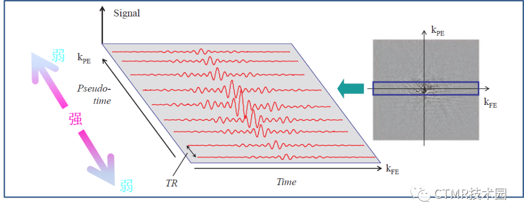
Suppose, however, that we apply a gradient continuously and measure or sample the MR signal at different time-points during the application of that gradient. At each point, the MR signal is affected by a different amount of gradient moment and has a different amount of phase change. Each data point therefore reflects a different amount of ‘phase encoding’ and thus corresponds to a different spatial frequency. We can therefore collect all the spatial frequencies for that direction from the evolving MR signal in real time following a single RF excitation. This is analogous to the phase-encode acquisition which works in ‘pseudo-time’, with a sampling separated by TR, as shown in Figure 8.17. The resulting raw data matrix is sometimes referred to as k-space.
然而,假设我们持续施加一梯度,在施加梯度的不同时间点测量/采集磁共振信号。在每一个时间点,磁共振信号所受的梯度矩的总量是不同的,同时累积的相位差也不同。因此每一个时间点反映了一个不同量值的“相位编码”,它对应着不同的空间频率。那么我们可以通过一次射频激发,采集随时间变化的磁共振信号,来获得这一方向上的所有空间频率。这个可以与相位编码采集进行类比,但相位编码的时间变化是“伪时间”,间隔 TR 时间进行采样,如图 8.17 所示。最终所采集的原始数据矩阵称作 k 空间。

So if we can do frequency encoding all at once, why waste all that time with multiple excitations and phase encoding? The answer is that frequency is a scalar parameter, i.e. it is described by a single number. If we applied frequency-encoding gradients in two directions at the same time we would have no way of knowing whether a particular frequency in the signal originated from one or the other (or both) of the applied gradients. By combining phase encoding and frequency encoding in two orthogonal directions we can collect all the spatial frequencies unambiguously that we need to make the image.
那么如果我们能施加一次频率编码就能采集所有频率编码方向的空间频率,为什么还要花费时间来进行多次激励和相位编码呢?因为频率是一个标量参数,即它是用单个数字表示的量。如果我们同时在两个方向施加频率编码梯度,那么我们没有方法知道信号中的某特定频率是来源于这两个梯度中的哪一个,亦或两者都有。通过在两垂直正交的方向联合相位编码与梯度编码,我们可以收集到成像所需要的明确的空间频率。
%%%%%%%%%%%%%%%
【译者注12】


%%%%%%%%%%%%%%%
Another way of understanding frequency encoding, more usually considered in texts, is to consider the effect of GFE on the frequency of the MR signal, illustrated in Figure 8.18.
还有另一种方式理解频率编码,这也是通常许多书中所使用的方法。就是考虑频率编码梯度对磁共振信号频率的作用效果,如图像 8.18 所示(即下图所示)。

Because the frequency-encode gradient is present at the same time as the MR signal is being measured, the signal’s frequency will now depend upon the position of the material from which it originated within the gradient field. It will not be a single sinusoid wave but a mixture of many frequency components. We then have a signal which is frequency encoded. It is easy to determine the frequency components; we simply perform another Fourier transform. Applied in one dimension this produces a spectrum which represents a one-dimensional projection of the object.
由于频率编码梯度施加的同时进行信号的采集,那么信号的频率将依赖于被扫描物质在梯度磁场中的位置。采集的信号将不再是单个正弦波,而是许多频率分量的混合,亦即这些信号被频率编码了。通过傅立叶变换可以轻易地测定频率成分。如果施加一维傅立叶变换,那么就得到物体的一维投影频谱。
%%%%%%%%%%%%%%%
【译者注13】

%%%%%%%%%%%%%%%
声明:由于本人才疏学浅,且篇幅较长,译注难免会有不当或错误的地方,还请各位老师多多指正。

不感兴趣
看过了
取消

人点赞

人收藏

打赏
不感兴趣
看过了
取消


 010-82736610
 股票代码: 872612
 京公网安备 11010802020745号


